Date:2026-08-07
Asking a supplier for "an AC contactor" without specifying the application is a bit like asking for "a fastener" without saying whether it needs to hold a shelf or a bridge. An AC contactor built for general remote motor control, one built specifically for capacitor bank switching, and one built with integrated overload protection are different enough in construction that treating them as interchangeable can lead to a mismatch between what a buyer orders and what a project actually needs. Understanding which AC contactor category a given application calls for, before comparing prices across suppliers, keeps buyers from specifying a device engineered for the wrong duty cycle.
A general-purpose AC contactor built for remote start and stop control of AC motors typically uses silver alloy contacts and an electromagnetic system rated for frequent operation across industrial equipment such as machine tools, fans, pumps, and conveyors. This class commonly operates within the AC-3 usage category, covering a current range that scales from smaller motor loads up to higher-capacity industrial equipment. Buyers should confirm rated operating voltage and current range against their specific motor's starting characteristics, since AC-3 rated contactors are engineered around the higher inrush current motors draw at startup, not just their steady-state running current.
Switching a capacitor bank puts a different kind of stress on a contactor than switching a motor does, since capacitors present a near-instantaneous inrush current at the moment of connection rather than the gradual ramp-up typical of motor starting. An AC contactor designed specifically for this duty needs stronger arc resistance and contact materials engineered to prevent welding under that inrush spike, which is why capacitor-switching contactors are built as a distinct product line rather than a general-purpose contactor with a higher rating applied. Buyers specifying contactors for power factor correction equipment or capacitor banks should confirm the product is rated specifically for capacitor switching duty, since a general-purpose contactor pressed into this role can fail prematurely even if its steady-state current rating looks sufficient on paper.
Some AC contactor lines integrate overload and short-circuit protection directly into the device, reducing the number of separate protective components a control panel needs to house. This integrated approach suits applications across machinery manufacturing, elevators, HVAC systems, and pumping stations, where panel space and wiring complexity are real design constraints. Buyers should clarify whether integrated protection replaces or supplements a separate overload relay in their control panel design, since assuming integrated protection eliminates the need for coordinated protective devices elsewhere in the circuit can create a gap in the overall protection scheme.
|
Series Type |
Primary Use Case |
Key Engineering Focus |
Typical Applications |
|
General remote-control |
Motor start/stop, AC-3 duty |
Reliable engagement, long mechanical life |
Machine tools, fans, pumps, conveyors |
|
Capacitor-switching |
Capacitor bank connection |
Arc resistance, anti-weld contacts |
Power factor correction, capacitor banks |
|
Integrated protection |
Combined switching and protection |
Overload and short-circuit response |
Elevators, HVAC, pumping stations |
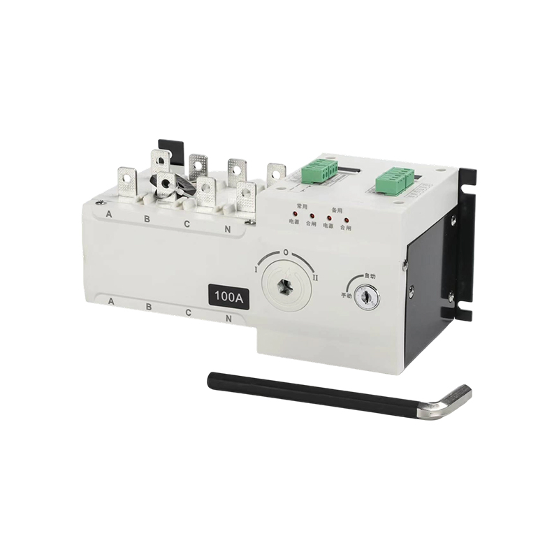
Facilities running multiple contactors in coordinated configurations, such as reversing motor control or transfer switching, often specify mechanical interlock options alongside or instead of purely electrical interlocking between devices. Mechanical interlocking provides a physical barrier against both contactors closing simultaneously, which protects against short-circuit conditions even if a control signal fault would otherwise allow both devices to energize at once. Buyers should discuss interlock requirements with their control panel designer early in the specification process, since retrofitting mechanical interlock hardware onto contactors not originally selected with that option in mind often requires replacing the devices rather than simply adding a bracket.
Coil power consumption affects both energy efficiency and how reliably an AC contactor engages across a range of control voltages, with low-power coil designs generally offering more consistent engagement across voltage fluctuations than higher-draw alternatives. Buyers should confirm coil voltage range and power draw against their specific control circuit design, particularly in installations where multiple contactors share a control transformer, since underestimating combined coil draw across several devices can leave a control circuit undersized for the total load it needs to support. This coil sizing question matters just as much for an AC contactor carrying built-in overload protection as it does for a general-purpose unit, since the added protection circuitry draws from the same control supply as the main coil.
 The company is committed to providing high-quality electrical products and excellent customer service. We not only supply exquisite, top-tier products to meet your needs but also back them with a sincere and comprehensive after-sales service guarantee.
Contact Us
 +86-18067486879
 [email protected]
 281 Wei 15th Road, Yueqing Economic Development Zone, Zhejiang, China
Copyright © Chengxi Electric Group Co., Ltd. All Rights
Reserved

High Voltage Transformer & Electrical Circuit Breaker Factory




 English
  Français
  中文简体
中文简体  русский
  Español
  عربى
عربى