Date:2026-07-31
Switchgear rooms rarely make headlines until something goes wrong, and one of the more consequential failure modes engineers guard against involves two power sources feeding the same bus simultaneously. Acb electrical interlocking exists specifically to prevent this scenario, and understanding why it works the way it does requires looking at how power distribution systems actually behave when multiple breakers share electrical proximity.
Two distinct approaches typically get combined within a single protection scheme. Mechanical interlocks physically block a breaker from closing when another connected breaker sits in a conflicting position, using linked shafts, cables, or key-exchange systems that make the wrong sequence physically impossible rather than merely discouraged. Acb electrical interlocking adds a parallel layer, using auxiliary contacts and control circuitry to achieve the same prevention electrically, so that even if mechanical linkage were somehow bypassed, the control circuit itself refuses to energize a closing coil under conflicting conditions.
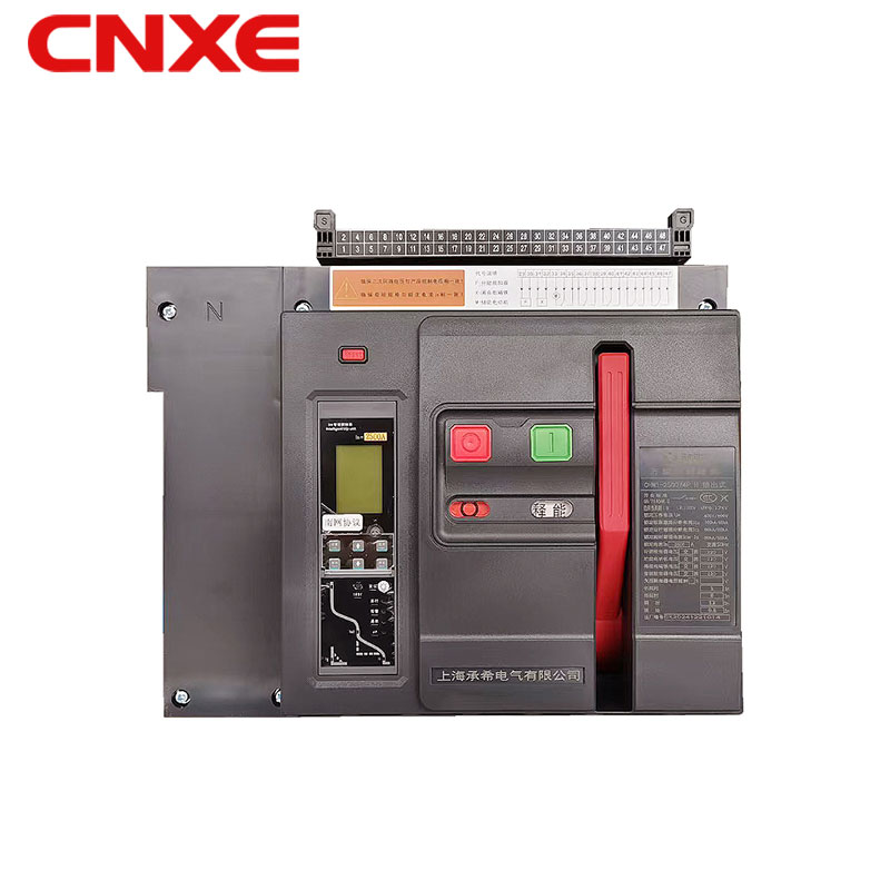
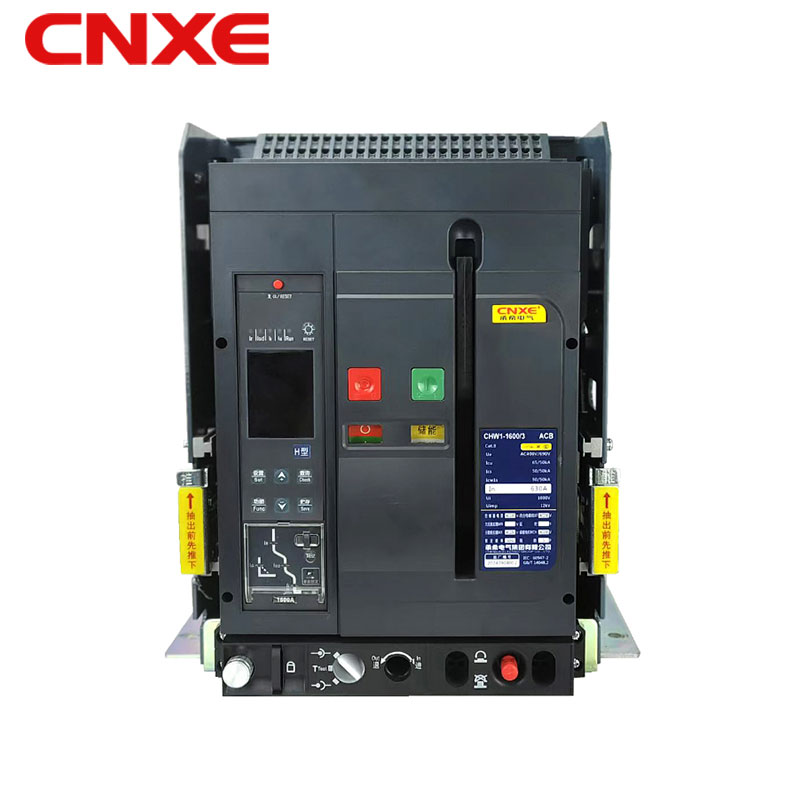
Which failure scenario does this dual approach address most directly? Generator and utility feed paralleling represents the clearest case, since closing both breakers simultaneously without proper synchronization creates a direct connection between two power sources that were never phase-matched, producing fault currents that can damage equipment far beyond the switchgear itself. Air circuit breaker assemblies handling this kind of dual-source configuration depend on interlocking to prevent operators from making that mistake, whether through oversight, miscommunication, or simple fatigue during a long shift.
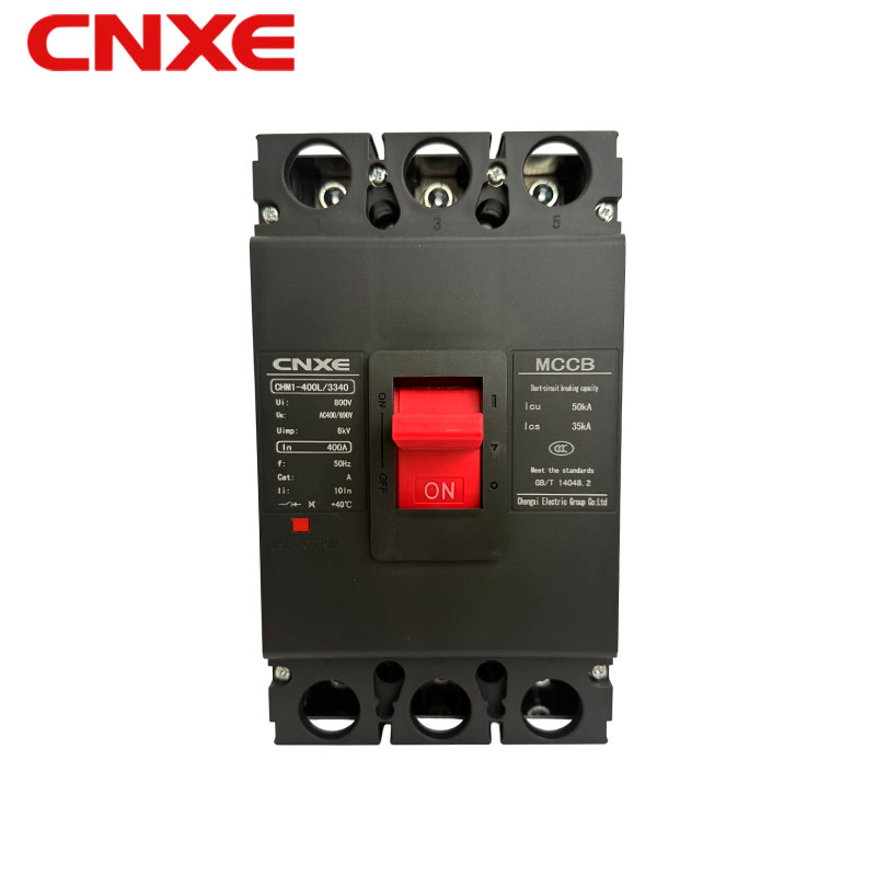
Bus coupler configurations present another scenario where acb electrical interlocking becomes structurally necessary rather than optional. Facilities running two independent buses with a tie breaker between them need to prevent both incoming breakers and the tie breaker from closing together under normal conditions, since that combination would parallel two potentially unsynchronized sources through the tie connection. Where does this configuration typically appear in industrial settings? Data centers and hospitals running dual utility feeds for redundancy rely on this exact arrangement, since losing one feed should trigger a controlled transfer sequence rather than an uncontrolled parallel condition that interlocking is specifically designed to prevent.
Do maintenance procedures introduce additional interlock requirements beyond normal operation? Draw-out breaker mechanisms add another layer, since a breaker withdrawn partway into its test position needs interlocking that prevents closing until it reaches a fully defined position, whether fully connected or fully isolated. A breaker caught in an intermediate position and allowed to close risks arcing across an improperly seated contact, which is why acb electrical interlocking schemes typically incorporate position-sensing auxiliary switches specifically for this transitional state.
Key interlock systems represent a widely used method for enforcing operational sequence across multiple breakers that cannot rely purely on electrical logic. Under this arrangement, a single transferable key must be physically moved between lock positions on different breakers, and the sequence of lock design ensures that only one breaker in a defined group can ever be free to close at a given moment. Where does this approach offer an advantage over purely electrical interlocking? Facilities with less sophisticated control wiring, or older switchgear installations retrofitted with acb electrical interlocking after initial construction, often favor key exchange systems since they provide a physically verifiable sequence without depending entirely on control circuit integrity that could degrade over years of service.
Beyond preventing incorrect breaker combinations, interlocking schemes increasingly coordinate with protective relay logic to add a supervisory layer above basic mechanical or electrical blocking. A switchgear protection scheme incorporating this coordination can factor in additional conditions, such as confirming synchronization check relay status before permitting a parallel closing operation, layering software-based verification on top of hardware interlocking rather than relying on hardware alone.
Which testing approach confirms that an interlock scheme performs correctly before a facility relies on it during actual operation? Functional testing during commissioning typically involves deliberately attempting every prohibited breaker combination to confirm the interlock blocks each one as designed, rather than testing only the permitted sequences. Facilities performing periodic maintenance often repeat abbreviated versions of this testing, since auxiliary contacts and control wiring supporting acb electrical interlocking can degrade gradually, and a scheme that passed commissioning testing years earlier deserves periodic reconfirmation rather than an assumption that it still functions exactly as originally installed.
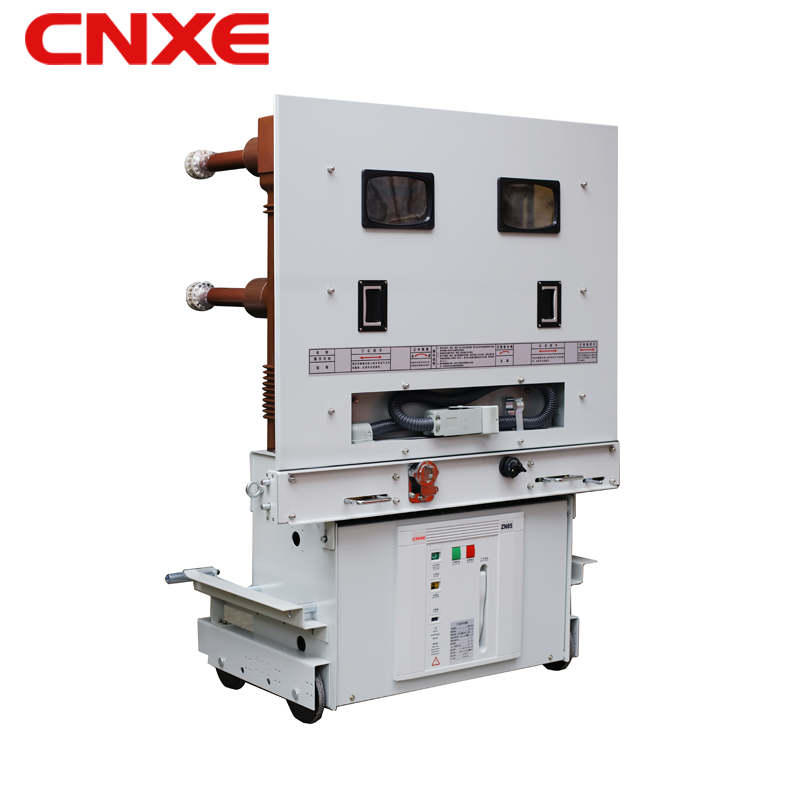
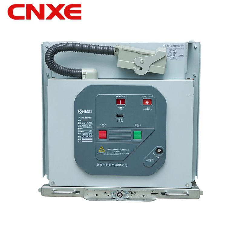
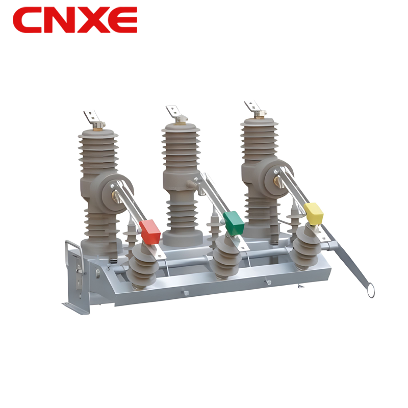
 The company is committed to providing high-quality electrical products and excellent customer service. We not only supply exquisite, top-tier products to meet your needs but also back them with a sincere and comprehensive after-sales service guarantee.
Contact Us
 +86-18067486879
 [email protected]
 281 Wei 15th Road, Yueqing Economic Development Zone, Zhejiang, China
Copyright © Chengxi Electric Group Co., Ltd. All Rights
Reserved

High Voltage Transformer & Electrical Circuit Breaker Factory




 English
  Français
  中文简体
中文简体  русский
  Español
  عربى
عربى